Home >> Products >> Educational Facilities >>LW-9540 Heat Exchanger Experiment
LW-9540 Heat Exchanger Experiment
Introduction
The main purpose of the experiment is to measure thermal performance of three typical heat exchangers under different flow directions and temperature conditions.
There are two flow directions - Parallel Flow and Counter Flow. Students can calculate Heat Capacity and temperature difference (LMTD), and then get total heat transfer coefficient (U).
If a larger total heat transfer coefficient appears under a constant condition, it means that the heat exchanger has better heat transfer performance.
Specifications
1. Three types of heat exchangers:
1.1 Double pipe
1.2 Plate
1.3 Shell and tube
2. Water circulation and control
2.1 A set of DC pump and flow meter 0 ~ 5 LPM
2.2 The flow rate is adjusted by manual valves.
2.3 Independent water tanks with constant temperature
a. Hot water tank: 60 ~ 80°C
b. Cold water tank: Ambient +5°C or the result of forced cooling
c. Made of stainless material
2.4 6 sets of T-Type sensors with digit displays to measure
a. Inlet and outlet temperatures of hot water
b. Inlet and outlet temperatures of cold water
c. Temperature in the hot water tank
d. Temperature in the hot water tank
3. With an operation platform and water-collecting structure
4. With a poster and instruction manual
5. Overall dimension: 0.6 (D) × 1.2 (L) × 1.4 (H) m (Ref.)
6. Power source: AC220V, 5A, single phase
Figures of Parallel and Counter Flow
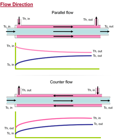

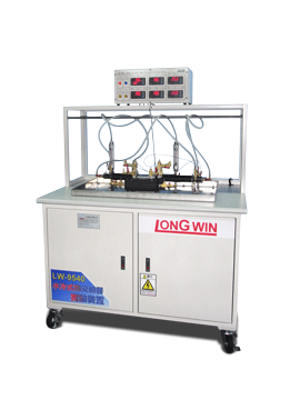
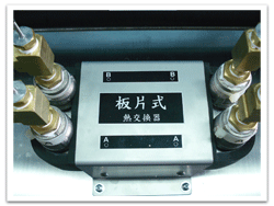
Plate heat exchanger
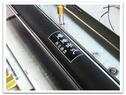
Double-pipe heat exchanger
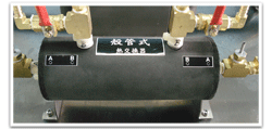
Shell-and-tube heat exchanger